
The amp is assembled and we are doing the real testing.
The initial tryout was with a Marshall 2x12 cab and my Gibson Nighthawk.
This amp is a little screamer. Fat, blooming overdrive. Tons of gain! Too much? This is where you get questions that will drive you crazy. Perspective is everything. What I'm loving is that it does like to take off, just grab a note and feed it back if you let it. Nice. Hit a note, bend it up, let the feedback catch, then slowly bend back and it catches the octave harmonic and feeds that back. Sweet.
That Nighthawk has a huge bridge Pup and the neck I have in there is no softy either. Hmmm, it sounds good, maybe great, but ... Some clean is essential. This starts breaking up real early. But it all works and well and the sound is there. Time to try it with the speaker and cab it will live with and more typical guitars.
In the cab with a Tele. Now we're talking. I can dial in however much gain I want off the guitar. Just set the volume on the amp for however much max gain I'll want, set that tone control to be as bright as I'd ever want and work the controls on the guitar. The tone control is very interactive with the volume, much the way a "bright" switch has little effect when the volume is turned up. Not a very severe affect either, just dials in more or less treble and bass. Nice.
Tried it with my Strat with Duncan Classic Live Wire, active pickups. It liked that too. Same with the Hamer with Rio Grande Bastard P90-ish pickups.
The overall tone is very open and broad and strongly reflects the guitar. Some amps tend to homogenize things, this one just makes the guitar louder and adds however much gain and overdrive you like.
The acid test -- how's it play in church? Perfectly well behaved. Was mostly clean for this set and it handled it very well. The Volume on the amp was around 10 o'clock and the guitar was mostly down for the clean stuff and only got wound up for one song. It behaved very nicely on the edge of break up. Many amps tend to give you something like a clean tone, but with fur on it. This was just a clear crunching tone at that point.
All in all, I'm gruntled and the amp ships soon.
Thursday, December 29, 2011
Tuesday, December 20, 2011
The Fenton Project VII
Everything is wired and time to test!!!!!
As with any new build or extensive overhaul it's best to power up slowly. A variac works well, to apply power gradually. I prefer the safety light approach. It reacts faster than I can read a current meter and it's more or less automatic. A 100 watt bulb will limit maximum current to something under one Amp and that is low enough that no serious damage would result from any problems.
Good thing I didn't trim the Output Transformer primary leads to length - as feared they were out of phase with the rest of the circuit and needed to be reversed. This is one of those things that are easier to identify with a function test than by pulsing the tranny and testing phase.
Now that everything works let's run it up on the scope and see what we get. Ooh, lots of gain. Bias check shows the power tubes dropping 13V across the 150 Ohm Cathode resistor; we've got 370V at the plate for a static dissipation of 15.5W per tube. A bit hot but no hotter than a lot of other EL84 amps. We'll run with this for now. Once we've got a baseline on the sound we'll see if cooling them off doesn't hurt.
Running it up into an 8 Ohm dummy load we get 18WRMS at 400Hz as the top and bottom of the waveform start to round off. Pretty much what you'd expect. Run a few different frequencies and some square wave to test the tone control. Time for a half power / one hour burn in. Everything appears solid and stable, nothing overheats and no extraneous noise appears on the 'scope.
Now for a real test - the test instrument is a Marshall 1936 2x12 cabinet. Plug in, power up, dead quiet. Turn everything up and there's the expected shhhhh of gain noise, but that's all there is no hum, sizzle or buzz. Now the guitar ...
Monday, December 19, 2011
The Fenton Project VI
We are close to the limits of my understanding of Roman Numerals (all of which is learned, like every American, from the Super Bowl) and my photographic limitations are taking a toll.
When we left off, I had connected the main power supply wiring, leaving the power cord for last so it wouldn't get in the way on the bench. Now it's time for the output transformer.

Early on, I was thinking to break out the wire lacing ribbon and go old-school HiWatt on it. However, the necessity of just getting this thing done sorta became a priority. The hand lacing is beautiful, but wire ties work too and since I'm only making one of these there isn't time to build the sort of wiring jig that would make lacing fast. You'll note that I left the primaries of the Output Tranny long enough to swap. Having had a painful formative experience with a mis-marked transformer I always do this until the phase is confirmed and then clean up the excess lead.

With the back of the amp wired up, now it's time to do the front. It's much easier to do this stuff without other things in the way. Yes, shielded wire on the low level stuff like from the input jack to the first stage and from the volume/tone controls back to the recovery stage. Why? Because I can. It doesn't cost much and could save time later. Anyone who has ever had to futz with the green wires in an old Marshall to get them exactly where they belong (just so high above the chassis, not near this, not too high) will understand.

So let's drop the board in and wire it up. Here is where the planning pays off. This part went fast and smooth enough I just got in a groove and neglected to take pictures.
 A little front end detail.
 Here she is ready for tubes and applied voltage.
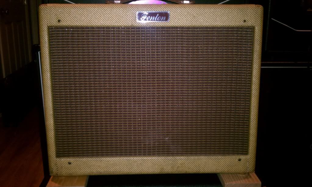
 There's the cute little back side. The stacked jacks are 4 Ohms. The only reason I could see for adding a pair of 8 Ohm jacks is to run a full stack. Doesn't look likely. But running this with an extension cab seems real probable so let's make it easy.

Pretty, isn't it. I like the big Alco knobs. I use them on everything. Great look and feel.
Next phase is to power up, do some testing and detailing on the wiring - then to fit it in the cab and rock out a little.
When we left off, I had connected the main power supply wiring, leaving the power cord for last so it wouldn't get in the way on the bench. Now it's time for the output transformer.

Early on, I was thinking to break out the wire lacing ribbon and go old-school HiWatt on it. However, the necessity of just getting this thing done sorta became a priority. The hand lacing is beautiful, but wire ties work too and since I'm only making one of these there isn't time to build the sort of wiring jig that would make lacing fast. You'll note that I left the primaries of the Output Tranny long enough to swap. Having had a painful formative experience with a mis-marked transformer I always do this until the phase is confirmed and then clean up the excess lead.

With the back of the amp wired up, now it's time to do the front. It's much easier to do this stuff without other things in the way. Yes, shielded wire on the low level stuff like from the input jack to the first stage and from the volume/tone controls back to the recovery stage. Why? Because I can. It doesn't cost much and could save time later. Anyone who has ever had to futz with the green wires in an old Marshall to get them exactly where they belong (just so high above the chassis, not near this, not too high) will understand.

So let's drop the board in and wire it up. Here is where the planning pays off. This part went fast and smooth enough I just got in a groove and neglected to take pictures.
 A little front end detail.
 Here she is ready for tubes and applied voltage.
 There's the cute little back side. The stacked jacks are 4 Ohms. The only reason I could see for adding a pair of 8 Ohm jacks is to run a full stack. Doesn't look likely. But running this with an extension cab seems real probable so let's make it easy.
Pretty, isn't it. I like the big Alco knobs. I use them on everything. Great look and feel.
Next phase is to power up, do some testing and detailing on the wiring - then to fit it in the cab and rock out a little.
Sunday, December 18, 2011
The Fenton Project V
Here we have the chassis drilled, punched and the first few bits mounted. Came up with a very nice NOS ceramic socket for the rectifier tube. Those get hot and this one won't care. Nice silver plated contacts, too. So it's time to start connecting stuff. This will work in layers, starting with heaters and primary power supply.
 And, a quick look underneath. What photo's can't show is the thought process behind laying this out. I tend to spend a lot of time thinking on these things, scribbling, shoving parts around and trying to reach the best of all the compromises involved. And the longer you go at that, the closer you get to very conventional, established practice. But, every detail you can improve does that much more to lower the noise floor and improve reliability and tone.

Once you mount the Power Transformer and start wiring things up the orientation of the tube sockets makes sense.

The basic rule of heater wiring is that you want to keep it away from signal wires. The two main approaches are to either keep the signals near the chassis and the heaters up in the air as in Fender amps. The other, more often British approach is to keep the heaters low and away from the signal circuits. Here they run to the corner of the chassis where the only wiring they'll be near is the Output Transformer primary and secondary. Neither is susceptible to noise pickup.

That big terminal strip is sort of a divider between the dirty and clean electrical environments inside the amp. On one end is the power cord "safety" ground and on the other is the chassis ground for everything else -- on one side is the raw AC and the secondaries of the power transformer on the other is everything else in the amp with the HV to the rectifier sneaking past.

Stay tuned for our next installment when we start with the next layer of wiring and connections.
 And, a quick look underneath. What photo's can't show is the thought process behind laying this out. I tend to spend a lot of time thinking on these things, scribbling, shoving parts around and trying to reach the best of all the compromises involved. And the longer you go at that, the closer you get to very conventional, established practice. But, every detail you can improve does that much more to lower the noise floor and improve reliability and tone.
Once you mount the Power Transformer and start wiring things up the orientation of the tube sockets makes sense.

The basic rule of heater wiring is that you want to keep it away from signal wires. The two main approaches are to either keep the signals near the chassis and the heaters up in the air as in Fender amps. The other, more often British approach is to keep the heaters low and away from the signal circuits. Here they run to the corner of the chassis where the only wiring they'll be near is the Output Transformer primary and secondary. Neither is susceptible to noise pickup.

That big terminal strip is sort of a divider between the dirty and clean electrical environments inside the amp. On one end is the power cord "safety" ground and on the other is the chassis ground for everything else -- on one side is the raw AC and the secondaries of the power transformer on the other is everything else in the amp with the HV to the rectifier sneaking past.

Stay tuned for our next installment when we start with the next layer of wiring and connections.
Sunday, November 27, 2011
The Fenton Project IV
Here's some background on the amp that's inspiring this project. No surprise that an obscure but excellent sounding amp has its own thread on The Gear Page.
Saturday, November 26, 2011
The Fenton Project III

Here's the populated board with all flying leads attached looking for a home. The circuitry for each stage follows in order and parallels the tube placement so there will be a minimum of crossing wires and nothing is close that can't run together.
In the interest of a neat layout nearly everything mounts to the board. The tone control network will mount on the back of the pots, very simple and neat and the signal from the tone and volume will run directly to the next tube stage through a shielded lead.
Grounds for the preamp section are all grouped and run together to the common buss at the main filter / decoupling cap.
Next we get the chassis drilled, hardware mounted and start with the off-board wiring.
Sunday, November 20, 2011
The Fenton Project II
I'm playing catch up a little here, so this comes right on the heels of the first post of the series.
Parts have arrived, the first to come in are the very solid looking ClassicTone transformers from Magnetic Components.

They are shown here with the chassis from Dirty Dawg Amps. Just for scale, that chassis is 17 inches wide and over 2-1/2 inches deep. These are chunky. The photo does not do justice to the finish and workmanship of the chassis. Brian does great quality, fast work at a very reasonable price. That's a theme throughout this project; we are looking for above average components at a reasonable price and combining them with a good layout and workmanship for a superior amp.
The next step is combining these parts into something like a guitar amp. For the layout process I like to have parts in hand and work out the plan on paper. I know a lot of people depend on computer assistance for this phase of the job, but I just feel more comfortable holding and measuring a part as I decide where it goes.
I'll confess, this is the slowest phase of any project for me. I tend to chew on these things forever until I'm sure that everything has been considered and all of the inevitable compromises are balanced appropriately.

After a few more sketches and some trial and error fitting I had a board and control panel layout and was ready to stake down some turrets.

Now, we're getting somewhere.
In the next post we'll have the board populated and be positioning things on the chassis. Then things get marked and the chassis goes under the drill press.
Monday, October 24, 2011
The Fenton Project
This is an interesting project. Commissioned by a fellow TGP'er, I am building an amp inspired by the Fenton 110. This is a variant on the classic 2xEL84 theme. Everybody and his kid brother has a Marshall 18W alike or Vox AC15-ish amp - this was different enough to be interesting and right in line with my experience with EL84 practice.
I had never heard of this company before - NB, this is not the vintage Fenton Weill - rather a small and now defunct builder. My client had tried this amp for a time and liked it, and now wanted one for himself but has been unable to find one.

A couple of things stand out about this design, and there are a few changes in store. Since we aren't going to be using the low gain input jack, that component will be omitted, which should make for better reliability (I've worked on a lot of JCM 800s with the complaint of "lo gain input works, hi gain doesn't). We're also making a change to the power supply. Our build will use some extremely beefy AC15 type iron from Magnetic Components. This means a 6CA4 rectifier tube instead of the 5Y3. The original used a Fender Deluxe Reverb type output tranny so this should be a good bit more solid.
The client has a very nice 1x12 cab that was previously occupied by a heavily modded Epiphone Valve Jr that the new amp will be designed to go into.

Updates to follow shortly.
Saturday, October 8, 2011
I'm Back
After a long time away, I am back and blogging again.
Just to kick things off, here's an interesting failure mode that came into my day job:

It's actually easier to plug that power cord into the XLR than into the power inlet jack where it belongs. Sometimes in a design you have to consider possibilities that seem impossible.
Subscribe to:
Posts (Atom)